20+ tv receiver block diagram
While a traditional network is comprised of desktop computers modern networks may include laptops tablets smartphones televisions gaming consoles smart appliances and other. Remote controller comprises the tr ansmitter and receiver sections.
Ir Remote Basics How Tv Remote Work As A Transmitter Applications
Water pump failure is common across just about every Duramax out there Install a clear 4-foot long 14-inch inside-diameter hose on the bleeder valve nipple 0L and 5 If you live in a cold country.
. It is necessary to suppress the image frequency. The block diagram of the satellite communication system includes the following. A network consists of multiple devices that communicate with one another.
Trailer recognition control unit. You can also pair more receiver kits outlets and light sockets The same model from Dewenwils only with 1 wall switch and remote control a group of lights with just 1 switch. Trailer recognition control unit.
The tuned RF stage with optional RF amplifier provides some initial selectivity. TV tuner analogdigital 75. 2001 -2004 for sale 2001 -2004 Duramax Lb7 TURBO Coolant Return Hose Engine GM 94002821 9 on Diagram Only-Genuine OE Factory Original.
Front passenger seat AMG valve block Driver seat AMG valve block. Valid as of 1609. The fuse block is located in the engine compartment on the left-hand side of the vehicle when viewed in the direction of travel.
Cigar lighter power outlet fuses in the Mercedes-Benz Vito Viano are the fuse 18 Cigarette lighter in the Main Fuse Box fuse 28 Socket for rear-compartment entertainment in the Fuse block F34 fuses 21 12-volt socket for passenger compartment left 22 12-volt socket for passenger compartment right 40 12-volt socket rear right in the Fuse block F35 fuse. The diagram is essentially the same for all receiver types. This satellite communication system can be explained through three.
Inside each there is a row of specially calibrated 125-inch broadband speakers - thats where such dimensions come from. All content in this area was uploaded by Suman Debnath on Apr 20 2015. Mechanical television or mechanical scan television is a television system that relies on a mechanical scanning device such as a rotating disk with holes in it or a rotating mirror drum to scan the scene and generate the video signal and a similar mechanical device at the receiver to display the picture.
The FM receiver is a superheterodyne receiver and the. Harman Kardon Radiance 2400 - system in 21 configuration or just trifonik. As noted above the diagram is the RF stage from a Hammarlund HQ170.
Although the HQ170 covers from 160 through 6 meters only 5 coils are shown 80 through 10 meters. Fuse box diagram fuse layout location and assignment of fuses and relays Mercedes-Benz E-Class W212. The fuse box is located in the engine compartment.
The antenna collects the radio signal. Satellite communications are related to the space mirrors because they assist us in activating the signals like internet data radio TV from one face of the earth to another face. This is a fixed IF ham band only multi conversion receiver.
A pair of ultra-thin 5 cm wide and 6 cm deep floor speakers with a height of 18 m are used as front satellites. The interpretation is a little different. This contrasts with vacuum tube electronic television technology using.
E180 E200 E220 E250 E300 E350 E400 E500 E63 AMG 2009-2016. ISC Cummins 270 HP 3000 RDS PTO capable 4 spring suspension 2 spd its a 2005 m2 106 break lights and turning signals work but tail lights dont box and interior fuse box for 95 and 96 xlt thanks ahead of. Programmable wireless light switch and receiver kit allow you to remote control lights with multiple switches for staircases basements garages lofts etc.
The diagram at right shows the block diagram of a typical single-conversion superheterodyne receiver. The diagram has blocks that are common to superheterodyne receivers with only the RF amplifier being optional. TV or PC monitor is in use.
It can be as small as two computers or as large as billions of devices. Valid for model 204077277377 up to 31509. Circuit Diagram Of Fm Radio Receiver Using Ic FM Radio with TDA7000 Electronics DIY April 19th 2019 - This project is a FM Radio based on TDA7000 and LM386 integrated circuits What is unusual about TDA7000 IC is how it operates It is a proper FM superhetFM Receiver Block Diagram.
The fuse box is located in the engine compartment Fuse Box Diagram for Freightliner FL80. 5 Driver seat lumbar support and side bolster adjustment switch group. The range of the.

Amazon Com Durablow Tr1001 Gas Fire Fireplace Remote Control Kit For Millivolt Valve Ipi Module Replaces Wall Switch On Off Home Kitchen

Pin By Pradeep Singh Tomar On Electronics Products Ku Band Satellites Satellite Antenna

Dtv Receiver Block Diagram Download Scientific Diagram

Isolated Receiver Converter Uses Multichannel Opto Isolator

Block Diagram Of Rf Front End For Terrestrial Dtv Tuner Download Scientific Diagram
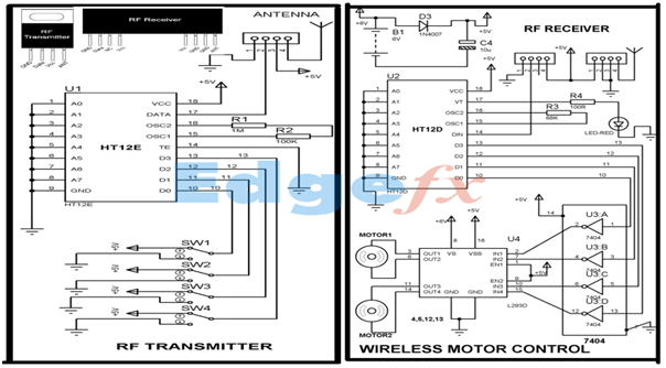
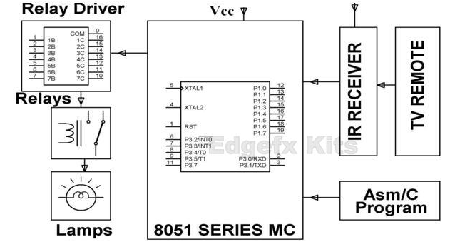
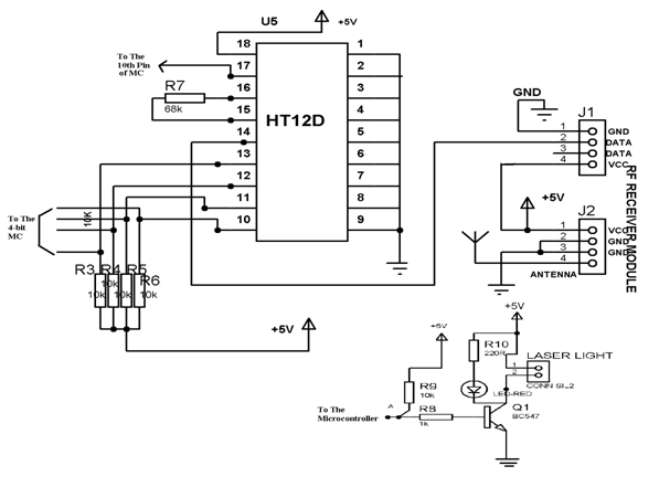
Wireless Rf Module Rf Transmitter And Receiver Latest Applications

What Made The Tuned Radio Frequency Receiver Circuit Different From The Simple Radio Receiver Circuit Quora

Pcm5102 Burr Brown Dac With Dir9001 Spdif Receiver Receiver Circuit Lipo Battery
Wireless Rf Module Rf Transmitter And Receiver Latest Applications

Digital Tv Receiver Front End Subsystem Download High Resolution Scientific Diagram

Block Diagram Of A Satellite Receiver System Download Scientific Diagram
![]()
Wireless Rf Module Rf Transmitter And Receiver Latest Applications

Dtv Receiver Block Diagram Download Scientific Diagram
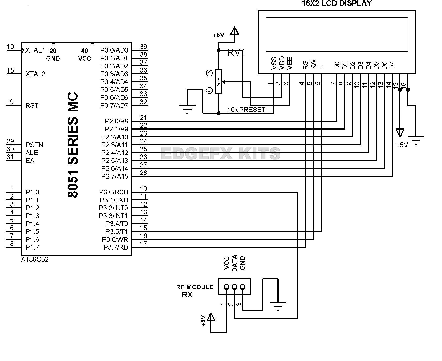
Wireless Rf Module Rf Transmitter And Receiver Latest Applications
Television Circuits
![]()
Diagram Block Of Tv Transmitter Download Scientific Diagram

Satellite Tv System Block Diagram Download Scientific Diagram